Specific energy
- 1 What is specific energy?
- 2 Specific energy equation
- 3 Do you still remember the Bernoulli equation?
- 4 Rectangular channel with $\alpha=1$
- 4.1 Critical depth and specific energy
- 4.2 Froude number
- 4.3 Specific energy diagram
- 4.4 Choke
- 4.5 Discharge diagram
- 4.6 Contractions and expansions with head loss
- 4.7 Head loss in an abrupt expansion
- 4.8 Head loss in gradual tapering of the expansion
- 4.9 Head loss in a contraction
- 4.10 Head loss in rivers
- 4.11 Homework: Rectangular channel expansion with head loss
- 5 Critical depth in non-rectangular sections
- 6 Overbank flow
- 7 Weirs
- 8 Homework: Choking, contraction, and transition
1 What is specific energy?
- Sum of depth and velocity head
- More formally, the height of the energy grade line above the channel bottom
2 Specific energy equation
\begin{equation} E=y+\frac{\alpha V^2}{2g} \label{eq:specific-energy} \end{equation} where
- $E$ is the specific energy,
- $y$ is the flow depth,
- $\alpha$ is the kinetic energy flux correction,
- $V$ is the mean cross-sectional velocity, and
- $g$ is the acceleration of gravity.
3 Do you still remember the Bernoulli equation?
I do!
\begin{align} \frac{p_1}{\gamma}+z_1+\frac{v_1^2}{2g} &=\frac{p_2}{\gamma}+z_2+\frac{v_2^2}{2g}\\ \frac{p}{\gamma}+z+\frac{v^2}{2g} &=C \end{align} where $C$ is a constant.
- Why is it constant?
- What does each of those terms mean?
- Which term is missing from the specific energy equation and why?
4 Rectangular channel with $\alpha=1$
For a rectangular channel with $\alpha=1$, Eq. (\ref{eq:specific-energy}) can be rewritten as \begin{equation} E=y+\frac{q^2}{2gy^2} \end{equation} where $q=Q/b$ and $b$ is the channel width.
4.1 Critical depth and specific energy
\begin{align} \frac{dE}{dy}&=1-\frac{q^2}{gy_c^3}=0\label{eq:dEdy}\\ y_c&=\left(\frac{q^2}{g}\right)^{1/3}\label{eq:yc} \end{align} \begin{equation} E_c=y_c+\frac{q^2}{2gy_c^2}=y_c+\frac{q^2}{gy_c^3}\frac{y_c}{2}=y_c+\frac{y_c}{2} =\frac{3}{2}y_c \label{eq:Ec} \end{equation} where $\dfrac{q^2}{gy_c^3}=1$ by Eq. (\ref{eq:dEdy}).
4.2 Froude number
From Eq. (\ref{eq:dEdy}), we can obtain \begin{equation} \frac{dE}{dy}=1-\left(\frac{q}{\sqrt{gy_c^3}}\right)^2=1-\mathbf{F}^2=0 \end{equation} where the Froude number $\mathbf{F}$ is defined as \begin{equation} \mathbf{F}=\frac{q}{\sqrt{gy^3}}=\frac{q/y}{\sqrt{gy}}=\frac{Q/(by)}{\sqrt{gy}}=\frac{Q/A}{\sqrt{gy}}=\frac{V}{\sqrt{gy}} \end{equation}
4.3 Specific energy diagram
Which of $q_g$ or $q_m$ is greater or less than $q_1$? Can you explain why?
4.4 Choke
If $\Delta z>\Delta z_c=E_1-E_c$, choking occurs where the upstream specific energy increases just enough to cause the critical flow condition at the downstream transition.
\begin{equation} y_1’+\frac{q^2}{2gy_1’^2}=E_c+\Delta z \end{equation}
Try Example 2.1.
4.5 Discharge diagram
See Figure 2.7.
4.6 Contractions and expansions with head loss
\begin{equation} y_1+\frac{Q^2}{2gA_1^2}=\Delta z+y_2+\frac{Q^2}{2gA_2^2}+K_L\left|\frac{1}{A_2^2}-\frac{1}{A_1^2}\right|\frac{Q^2}{2g} \end{equation}
4.7 Head loss in an abrupt expansion
For the head loss in an abrupt open channel expansion assuming $y_1=y_2$, Henderson’s (1966) analysis shows: \begin{equation} h_L=\frac{V_1^2}{2g}\left[\left(1-\frac{b_1}{b_2}\right)^2+\frac{2\mathbf{F}_1^2b_1^3(b_2-b_1)}{b_2^4}\right] \end{equation} where $b_2>b_1$ (expansion).
For $\mathbf{F}_1<0.5$, the second term is negligible and \begin{equation} K_L =\frac{\frac{V_1^2}{2g}\left(1-\frac{b_1}{b_2}\right)^2}{\left|\frac{1}{A_2^2}-\frac{1}{A_1^2}\right|\frac{Q^2}{2g}} =\frac{\frac{V_1^2}{2g}\left(1-\frac{b_1}{b_2}\right)^2}{\left|\frac{V_2^2}{2g}-\frac{V_1^2}{2g}\right|} =\frac{\left(1-\frac{b_1}{b_2}\right)^2}{\left|\frac{V_2^2}{V_1^2}-1\right|} =\frac{\left(1-\frac{b_1}{b_2}\right)^2}{1-\frac{b_1^2}{b_2^2}} =\frac{1-\frac{b_1}{b_2}}{1+\frac{b_1}{b_2}} \label{eq:KL-abrupt-expansion} \end{equation}
4.8 Head loss in gradual tapering of the expansion
At a rate of 1:4 (lateral:longitudinal), $K_L\approx 0.3$ of Eq. (\ref{eq:KL-abrupt-expansion}).
4.9 Head loss in a contraction
Less than an expansion.
According to Henderson (1966),
- $h_L=0.11\frac{V_2^2}{2g}$ in a rounded contraction and
- $h_L=0.23\frac{V_2^2}{2g}$ in a square-edged contraction.
4.10 Head loss in rivers
The HEC-RAS manual (2016) suggests
- $K_L=0.3$ for a gradual expansion and
- $K_L=0.1$ for a gradual contraction.
The default values for WSPRO are
- $K_L=0.5$ for an expansion and
- $K_L=0.0$ for a contraction.
4.11 Homework: Rectangular channel expansion with head loss
There is a rectangular channel with a negligible slope but with an expansion. The upstream side is 2m wide and 2m deep with a velocity of 3.75m/s. The downstream side expands to a width of 2.51m and is raised by 0.25m. Determine the flow depth at the downstream location. Use a head loss coefficient ($K_L$) of 0.4.
5 Critical depth in non-rectangular sections
\begin{equation} E=y+\alpha\frac{Q^2}{2gA^2} \end{equation} where $A$ is the cross-sectional area.
In an irregular cross section, $A(y)$ and $B(y)$ (top width) are functions of $y$.
By differentiating $E$ with respect to $y$ and setting it to 0 for the minimum specific energy, we obtain \begin{equation} \frac{dE}{dy}=1-\frac{\alpha Q^2}{gA^3}\frac{dA}{dy}=0 \end{equation}
$B=\frac{dA}{dy}$ from Figure 2.12 results in \begin{equation} \frac{\alpha Q^2B_c}{gA_c^3}=1 \end{equation} where $c$ indicates the critical condition.
5.1 Froude number in non-rectangular sections
Define the hydraulic depth $D=\frac{A}{B}$.
\begin{equation} \mathbf{F}=\sqrt{\frac{\alpha Q^2B}{gA^3}}=\sqrt{\frac{Q^2/A^2}{gA/B/\alpha}}=\frac{V}{\sqrt{gD/\alpha}} \end{equation}
5.2 Minimum specific energy in non-rectangular sections
\begin{equation} E_c=y_c+\alpha\frac{Q^2}{2gA_c^2}=y_c+\frac{\alpha Q^2B_c}{gA_c^3}\frac{A_c}{2B_c}=y_c+\frac{D_c}{2} \end{equation}
5.3 Homework: Derivation of Eq. (2.23)
Derive Eq. (2.23) in the text. Show your full work.
5.4 Example 2.2
Find the critical depth using the graphical and numerical methods.
5.5 Example 2.3
This channel gradually contracts in width to a trapezoidal channel with the same side slopes and bottom elevation but having a bottom width of 4 m. What is the contracted flow depth neglecting the head loss?
6 Overbank flow
River banks are typically more vegetated and tend to have higher Manning’s roughness coefficients than the main channel.
In an overbank flow, $\alpha$ can no longer be considered a constant because of large non-uniformities between the main channel and overbank flow velocities.
$\alpha$ varies with $y$!
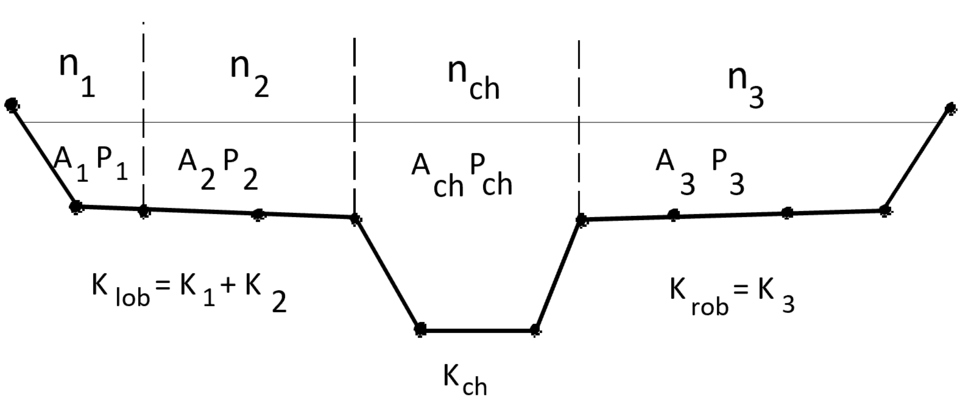
This type of a channel is called a compound channel. See Figure 2.16.
6.1 Conveyance calculation for a compound channel
Conveyance is the discharge per square root of the energy gradient: \begin{equation} K=\frac{Q}{S_e^{1/2}} \end{equation} where $S_e$ is the slope of the energy grade line, usually the slope of friction loss $S_f$.
6.2 Specific energy for a compound channel
We start with \begin{equation} dE=\frac{\partial E}{\partial y}dy+\frac{\partial E}{\partial A}dA+\frac{\partial E}{\partial\alpha}d\alpha \end{equation} where $\frac{\partial E}{\partial y}=1$, $\frac{\partial E}{\partial A}=-\frac{\alpha Q^2}{gA^3}$, and $\frac{\partial E}{\partial\alpha}=\frac{Q^2}{2gA^2}$.
Then, \begin{equation} \frac{dE}{dy}=1-\frac{\alpha Q^2B}{gA^3}+\frac{Q^2}{2gA^2}\frac{d\alpha}{dy} \label{eq:compound-channel-specific-energy} \end{equation} where $B=\frac{dA}{dy}$.
6.3 Compound channel Froude number
By setting Eq. (\ref{eq:compound-channel-specific-energy}) to 0 and taking its square root, we can define the compound channel Froude number by \begin{equation} \mathbf{F}_c=\left(\frac{\alpha Q^2B}{gA^3}-\frac{Q^2}{2gA^2}\frac{d\alpha}{dy}\right)^{1/2} \end{equation} where subscript $c$ indicates a “compound” channel.
Using the definition of $\alpha=\frac{\int_A v_s^3\,dA}{V_s^3A}$, we can express the compound $\alpha$ as \begin{equation} \alpha=\frac{\sum_i(Q_i/a_i)^3a_i}{(Q/A)^3A}=\frac{\sum_i(k_i^3/a_i^2)}{K^3/A^2} \end{equation}
See Eqs. (2.32) and (2.33).
6.4 Multiple critical depths
See Figures 2.17, 2.18, and 2.20.
The bank-full Froude number for the main channel is defined by \begin{equation} \mathbf{F}_1=\frac{QB_1^{1/2}}{g^{1/2}A_1^{3/2}} \label{eq:F_1} \end{equation} where subscript $1$ refers to bank-full values of the geometric parameters, and $B_1$ and $A_1$ are the bank-full top width and area, respectively.
For critical flows with $\mathbf{F_c}=1$, $\mathbf{F_c}/\mathbf{F_1}=1/\mathbf{F_1}$ in Figure 2.20 decreases with an increasing $Q$. At $\mathbf{F_c}/\mathbf{F_1}=1$, the upper limit of the discharge $Q_U$ occurs and, at $(\mathbf{F_c}/\mathbf{F_1})_\text{max}$, the lower limit of the discharge $Q_L$ occurs.
6.4.1 Discharge limits for multiple critical depths
To find the upper limit of the discharge $Q_U$ for multiple critical depths, we use $\mathbf{F}_1=1$ to derive \begin{equation} Q_U=\frac{\sqrt{g}A_1^{3/2}}{\sqrt{B_1}}. \label{eq:Q_U} \end{equation}
To find its lower limit $Q_L$, we plug $Q=Q_L$ into Eq. (\ref{eq:F_1}) to express $\mathbf{F}_1$ in terms of $Q_L$ and $Q_U$, and derive \begin{equation} \mathbf{F}_1=\frac{Q_LB_1^{1/2}}{g^{1/2}A_1^{3/2}}=Q_L\left(\frac{\sqrt{g}A_1^{3/2}}{\sqrt{B_1}}\right)^{-1}=\frac{Q_L}{Q_U} \end{equation} and, for the lower limit critical flow $Q_L$ with $\mathbf{F_c}=1$, $\mathbf{F_c}/\mathbf{F_1}=1/\mathbf{F_1}$ becomes \begin{equation} \left(\frac{\mathbf{F}_c}{\mathbf{F}_1}\right)_\text{max}=\frac{Q_U}{Q_L}. \end{equation}
6.5 Example 2.4
7 Weirs
Weirs result in a critical flow condition by obstructing open channel flow. They are useful for measuring the flow rate.
7.1 Sharp-crested rectangular notch weir
Assumptions
- No head losses
- Atmospheric pressure across the section above the weir crest
- No vertical contraction of the nappe (a sheet of water flowing over the weir)
See Figure 2.22.
\begin{equation} v=\sqrt{2gh} \end{equation}
\begin{equation} q_t =\int dq =\int_\frac{V_0^2}{2g}^{\frac{V_0^2}{2g}+H}\sqrt{2gh}\,dh =\frac{2}{3}\sqrt{2g}\left[\left(1+\frac{V_0^2}{2gH}\right)^{3/2}-\left(\frac{V_0^2}{2gH}\right)^{3/2}\right]H^{3/2} \label{eq:sharp-crested-rect-weir} \end{equation} which is the flow rate per weir width.
7.2 Sharp-crested rectangular notch weir equation
From Eq. (\ref{eq:sharp-crested-rect-weir}), \begin{equation} Q=\frac{2}{3}\sqrt{2g}C_dLH^{3/2} \end{equation} where $C_d$ is the discharge coefficient, which can only be determined experimentally.
See Figure 2.23 and Table 2.3.
7.3 Sharp-crested triangular notch weir
See Figure 2.24.
\begin{equation} Q =\int dQ =C_d\int_\frac{V_0^2}{2g}^{\frac{V_0^2}{2g}+H}\sqrt{2gh}\left[2\left(\frac{V_0^2}{2g}+H-h\right)\tan\frac{\theta}{2}\right]\,dh \end{equation}
For the V-notch weir, assume $V_0\approx 0$. \begin{equation} Q =C_d\int_0^H\sqrt{2gh}\left[2\left(H-h\right)\tan\frac{\theta}{2}\right]\,dh =C_d\frac{8}{15}\sqrt{2g}\tan\frac{\theta}{2}H^{5/2} \end{equation}
7.4 Broad-crested weir
See Figure 2.25.
\begin{equation} H_e=H+\frac{V_0^2}{2g}=y_c+\frac{Q^2}{2gA_c^2}=\frac{3}{2}\left[\frac{(Q/L)^2}{g}\right]^{1/3} \end{equation} from Eqs. (\ref{eq:yc}) and (\ref{eq:Ec}) (Eqs. (2.6) and (2.7) in the text).
\begin{equation} Q =C_d\frac{2}{3}\left(\frac{2}{3}g\right)^{1/2}LH_e^{3/2} =C_vC_d\frac{2}{3}\left(\frac{2}{3}g\right)^{1/2}LH^{3/2} \end{equation} where the approach velocity coefficient $C_v=(H_e/H)^{3/2}$.
7.5 Submerged rectangular weir
See Figure 2.27 and Eqs. (2.50)–(2.52).
7.6 Homework: Example 2.5
- Example 2.5
Show your full work.
8 Homework: Choking, contraction, and transition
- Exercise 2.1
- Exercise 2.3
- Exercise 2.7
Show your full work.

