\[ \newcommand\si[1]{\mathrm{#1}} \newcommand\SI[2]{#1\,\si{#2}} \newcommand\matr[1]{\mathbf{#1}} \DeclareMathOperator*{\argmax}{arg\,max} \DeclareMathOperator*{\argmin}{arg\,min} \]
How to convert LiDAR data in the LAS file format to surface models in ArcGIS Pro
1 LAS file format
LAS (LASer) is an open, binary file format specified by the American Society for Photogrammetry and Remote Sensing (ASPRS) to archive point cloud data collected by the Light Detection and Ranging (LiDAR) surveying technology.
2 LAZ and zLAS?
There are two other file formats called LAZ and zLAS. LAZ is an open, compressed version of the LAS format while zLAS is Esri’s proprietary “optimized” version of LAS.
Please read the LiDAR format letter by the Open Source Geospatial Foundation (OSGeo) delivered to the LiDAR community and related companies including Esri. Please also read five myths about LAS, LAZ, and “Optimized LAS”.
3 Available LAS files
We can freely download LAS data for the United States from the National Map by USGS or OpenTopography by the OpenTopography Facility.
4 What do LAS data look like?
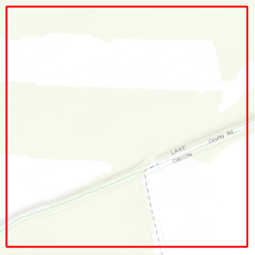
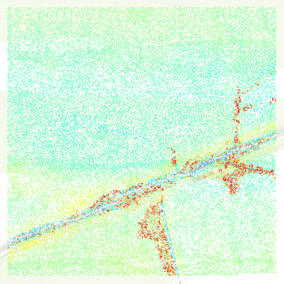
LAS files contain point cloud data (“a lot” of points). When you add a LAS file to ArcGIS Pro, you may just see a red rectangle that shows the extent of the data when zoomed out, or actual points when zoomed in enough.
5 LAS tools in ArcGIS Pro
ArcGIS Pro provides many geoprocessing tools that can handle LAS files. We mainly focus on data conversion in this exercise. LAS data conversion tools include
- LAS Dataset to Raster
- LAS Dataset to TIN
- Build Terrain: This tool requires some other tools to be run first in the following order:
- Create Feature Dataset
- Create Terrain
- Add Terrain Pyramid Level
- LAS To Multipoint
- Add Feature Class To Terrain
- Build Terrain
6 LAS Dataset to Raster
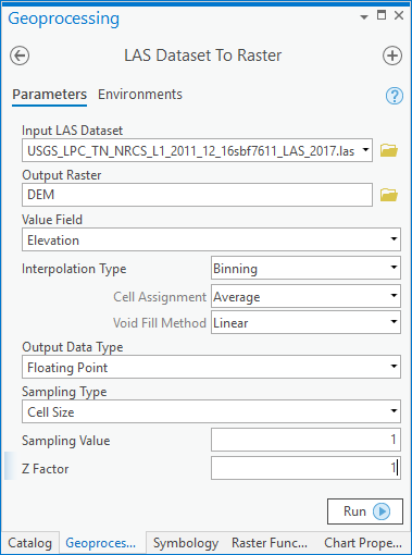
This tool converts point cloud data in LAS to the Digital Elevation Model (DEM) in the raster format. It fills voids between points by interpolation and creates an elevation surface model. There are different interpolation methods. The resolution of the output raster is determined by the sampling type and value parameters. Please refer to the tool help page for more details.
The Z factor is mainly used to convert the unit of elevation to another. Since this tool does not reproject the original LAS data, probably, it is a good idea to keep the original unit. Check the metadata file first to see what coordinate system and vertical unit your data is in.
7 LAS Dataset to TIN
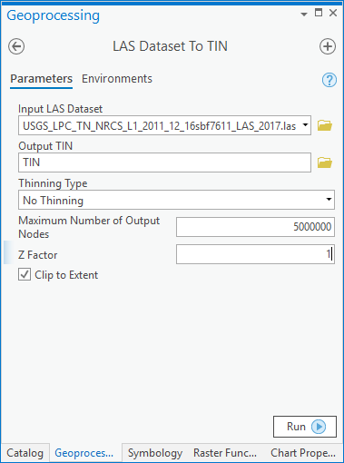
This tool converts point cloud data to the Triangulated Irregular Network (TIN) model. You may need to reduce the maximum number of output nodes or “thin” point cloud data to successfully run it.
The TIN is a single-resolution dataset, which means that the number of triangles in its network does not change or its source point data does not get “thinned” no matter what scale your map is at. If there are a lot of triangles, rendering this type of data can be slow when the map is zoomed out to the full extent of a TIN. Esri developed a new dataset called terrain to address this performance issue. Terrain is a multi-resolution dataset based on the TIN.
8 LAS to Terrain
Creating a terrain dataset from LAS point cloud data is a multi-step process. For this conversion, let’s reproject the LAS data into a State Plane coordinate system in US feet.
8.1 Create Feature Dataset
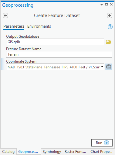
The very first step in creating a new terrain is to create a container that holds source data including point cloud, break lines, etc. A feature dataset is a group of feature classes inside a geodatabase. Using State Plane Zones.zip, figure out which State Plane coordinate system you have to use (NAD 1983 please) and choose that coordinate system in the Create Feature Dataset tool: the global icon next to Coordinate System → Projected coordinate system → State Plane → NAD 1983 (US Feet) → Your State Plane projection.
8.2 Create Terrain
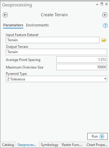
Now, you can create a new empty terrain in the feature dataset you created from the last step. For the average point spacing, you need to find point density/spacing information from the metadata file. If it’s not available, measure the distance between points in the LAS layer and calculate this parameter. This parameter needs to be in the unit of the feature dataset. Since we use a State Plane projection in this exercise, it should be in feet. I converted 0.4 meter to 1.312 feet, and typed 1.312. Also, for this exercise, let’s use the Z-tolerance pyramid type, which creates multiple pyramid levels based on the vertical accuracy relative to the full resolution of the data.
8.3 Add Terrain Pyramid Level
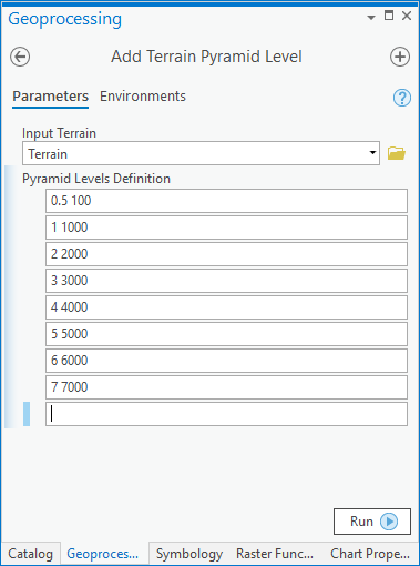
In this tool, we can define multiple pyramid levels. Since we use the Z-tolerance pyramid type, the screenshot to the left defines a pyramid level 0.5 at scale 1:100. It means that the maximum vertical error at a scale smaller than or equal to 1:100 will be 0.5 foot. Remember we use a State Plane projection, hence the accuracy in feet.
8.4 LAS To Multipoint
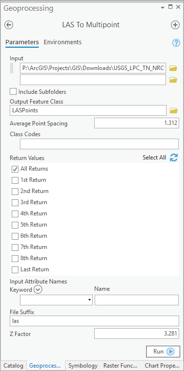
We need to export point cloud data from LAS into a point feature class. The LAS to Multipoint tool converts LAS to a multipoint feature class. The output feature class needs to be created inside the feature dataset from the previous step. The average point spacing parameter needs to be specified in the unit of the output coordinate system, which is feet in our case. It is 0.4 meter or 1.312 feet. Since we already assigned a State Plane coordinate system to the feature dataset, the tool doesn’t even display the coordinate system parameter. For the Z factor, we want to enter 3.281 to convert meters to feet. That is, 3.281 feet per meter. It will create a 3-dimensional multipoint feature class.
8.5 Add Feature Class To Terrain
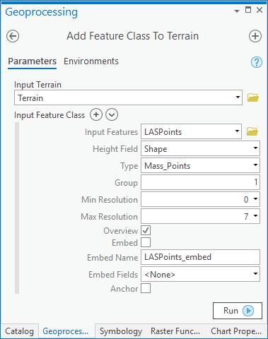
Now, let’s add the multipoint feature class to the terrain. Since we use a 3-dimensional multipoint feature class, the height field is Shape and the type is Mass_Points. The tool automatically populates pyramid level information. For this exercise, we won’t add breaklines.
8.6 Build Terrain
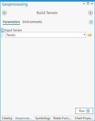
Finally, it’s time to build the terrain. This tool looks very simple because all the preparation tasks were done in the other tools, but it’ll probably take the longest because it does the heavy lifting of filtering points for different pyramid levels and building the actual surface model.
8.7 Testing the terrain
You can find the new terrain from your project geodatabase under the Terrain feature class. It’s named Terrain.
